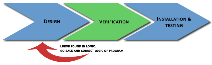
The Logic Error Hunter is a software tool for automated functional verification, validation and testing
of PLC control logic. It is based on most advanced formal verification methods proprietary to our company only.
By applying the tool, PLC program reliability and functional safety are achieved
in early project development stages. It saves time and money in later stages of the program life cycle,
such as deployment and commissioning.
The testing is based on developing (auto generating) a number of verification
tests. These are logic test conditions verifying the correctness of behavioural
properties for PLC program logic. An example of a test condition for instance would be:
"verify that the spindle motor of a CNC milling machine can never be started while the
emergency stop button is activated" (in LEH syntax: "always[[not]SP_MOT_01 and EM_STOP]).
Yet another example of a test condition would be: "verify that both directions of an
asynchronous motor can never be "on" at the same time (in LEH syntax: "never[MOTOR_CW and MOTOR_CCW]).
Every test returns a result of "true" or "false" after running it on the PLC program logic.
A rendered "true" result after test execution, assumes for instance, that there
is no logic error in the verified PLC program where a "false" result indicates an error.
Individual tests for a PLC program are packaged in a test suite and executed in a batch to verify the
whole functionality of the program.
The mechanism behind the Logic Error Hunter verification/testing is based
on formal verification methods and guarantees the delivery of logic error free PLC programs.
For further technical details on the Logic Error Hunter please refer to the "Videos" and
"Doownloads" pages on this web site where you can find brochures, demos in the form of videos and
power point presentations as well as an evaluation copy of the product.
Area Of Applicability
The product is applicable for all kinds of industrial automation applications
such as process control, machine control, manufacturing, material processing,
automated production lines, HVAC, oil and gas, water treatment/supply etc.
It is suitable for the verification of all kinds of behavioral logic patterns
such as sequence logic, state machine logic, logic executing in parallel,
interlocks verification, alarms/faults verification etc.)
PLC Programs can be written in Ladder Logic, Structured Text, Function Blocks, SFC
and can use standard or user defined instructions.
The Logic Error Hunter can handle any size PLC programs.
As already mentioned, by encapsulating a powerful formal logic verification methodology with
close to zero error tolerance, the tool enables the development of
PLC control logic for safety critical applications.
The verification is exhaustive and if there is a problem with the logic, it is guaranteed
that it will be found and reported to the user. The usage of the product leads
to increased reliability and quality of the delivered PLC program.
Testing by the push of a button
At the push of a button and in very few seconds, common but difficult to track
down PLC program logic errors can be detected. Errors like missing interlocks,
multiple destructive usages of PLC tags, race conditions, unreachable logic
states can be uncovered without the need for tedious simulations and test scenarios.
Note that most tests for a PLC program in the Logic Error Hunter are auto generated.
Cost savings in the program development stage
The Logic Error Hunter can be customized to auto generate tests out of functional specifications
binding functional requirements with the testing this way. Auto generating the tests means close to
0 time spend in Factory Acceptance Testing.
Cost effective commissioning of PLC applications
PLC program developers can avoid situations where they need to deal with nasty
surprises during the commissioning and acceptance testing phase.
PLC LEH can save millions of dollars in replacing of damaged equipment caused by faulty PLC code,
commissioning delays due to late discovery of PLC code errors and unexpected program behavior.
Cost effective PLC code upgrade and maintenance
While verifying the logic in the development phase with LEH, you
also create a regression test suite used all the way along the lifecycle
of a PLC program. The test suite is reused after upgrades to verify that existing logic has not
been compromised.
No need for sophisticated testing facilities
It is a tool purely implemented in software allowing verification and validation of a PLC
program with virtually no equipment required and in much shorter time compared
to simulation techniques used for the purpose.
Powerful debugging facilities
The LEH possesses powerful program debugging facilities such as program single step execution,
execution stop on break conditions, signal trending and timing diagrams generation to mention a few.
Development risk management
Using the tool, the developer gets familiar with the behavior of the program
very early in the design stage and manages much better the risk of
late detection of missing functionality in the PLC code.
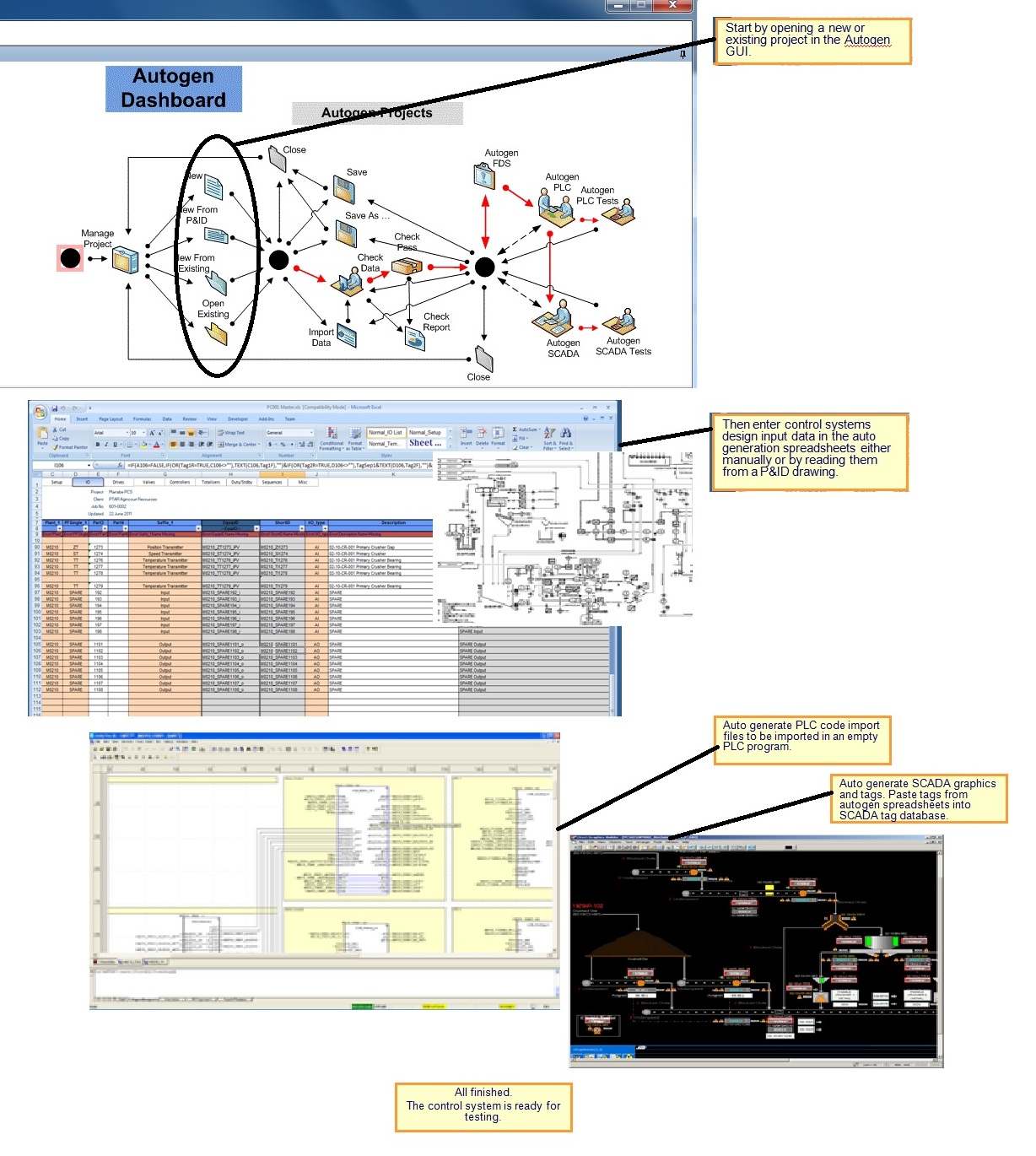
Control Systems Auto Generation is a software product allowing engineers to produce
a complete control system (PLC code, SCADA code and accompanying documentation like
Functional Specification, Alarm Tables, Trigger - Action Tables,
FAT/SAT test documents and test scripts for automated testing)
from a set of design input data records provided by the control systems
vendor in the form of PnID, Excel spreadsheets, or text documents.
Generally in the design input data set the following is specified:
PLC I/O points - Records specifying Digital/Analog Inputs/Outputs connected to PLCs;
Records specifying lists of plant facilities of different variety controlled by the system like motors, valves and their control parameters;
Records of control systems entities like PID controllers, Control Sequences, Control state machines, Duty/Standby selectors and their parameters;
List of PLCs used, their types and configuration and memory map;
List of SCADA pages and the respective division of controls in them.
Currently, for auto generation purposes, design input data is stored in Excel spreadsheets,
but it can be provided in the form of Access data bases or SQL databases.
The auto generation process is based on the usage of templates for all of its produced output.
These are generic text forms for code or document generation with tag place holders.
In the auto generation process tag place holders are replaced with effective tags specified in the design input data.
The Auto gen tool is a standard Windows program coming with a standard Windows Installer.
In addition it requires Microsoft Office 2003, 2007 or 2010.
Auto Generation Overview
The Benefits of Using Auto Generation
Takes off all the repetitive work that engineers have to put up with in order to manually code a control system.
Control Systems development time reduced by up to 80%. It is simply a matter of entering all the design input data required for auto generation.
Generates high quality, reliable, well structured and easy to maintain code and documentation.
Capable of auto generating parts of the control system (e.g. generating PLC code and SCADA
graphics only for few or a single control item like a motor, valve, PID controller).
It makes the process of modifying the control system very easy.
Flexible enough to auto generate code and documentation according to any customer standards and requirements.
Easily customizable to suit customer standards and format requirements.
Capable of generating PLC code for any PLC brands, SCADA graphics and tags for several
SCADA vendor brands, Functional Design Descriptions in Microsoft Word or other format ,
alarming tables, event action control tables, test patterns for automated PLC code testing,
FAT documentation, SAT documentation and other customer required code or documentation.
Factory Acceptance Testing reduced by 50% since no typing or tag address mapping errors are
expected between SCADA and PLC because tag addresses are automatically calculated.
Same applies to Site Acceptance Testing too.